

-
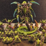
The Tyranid Swarm
-
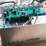
Rubidium GPSDO
-
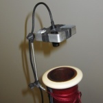
Acoustic Bassoon Pickup
-
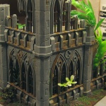
Warhammer 40k Terrain
