


-
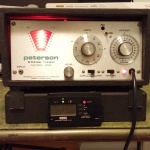
Strobe Tuner Refurb
-
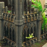
Warhammer 40k Terrain
-
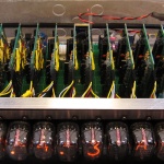
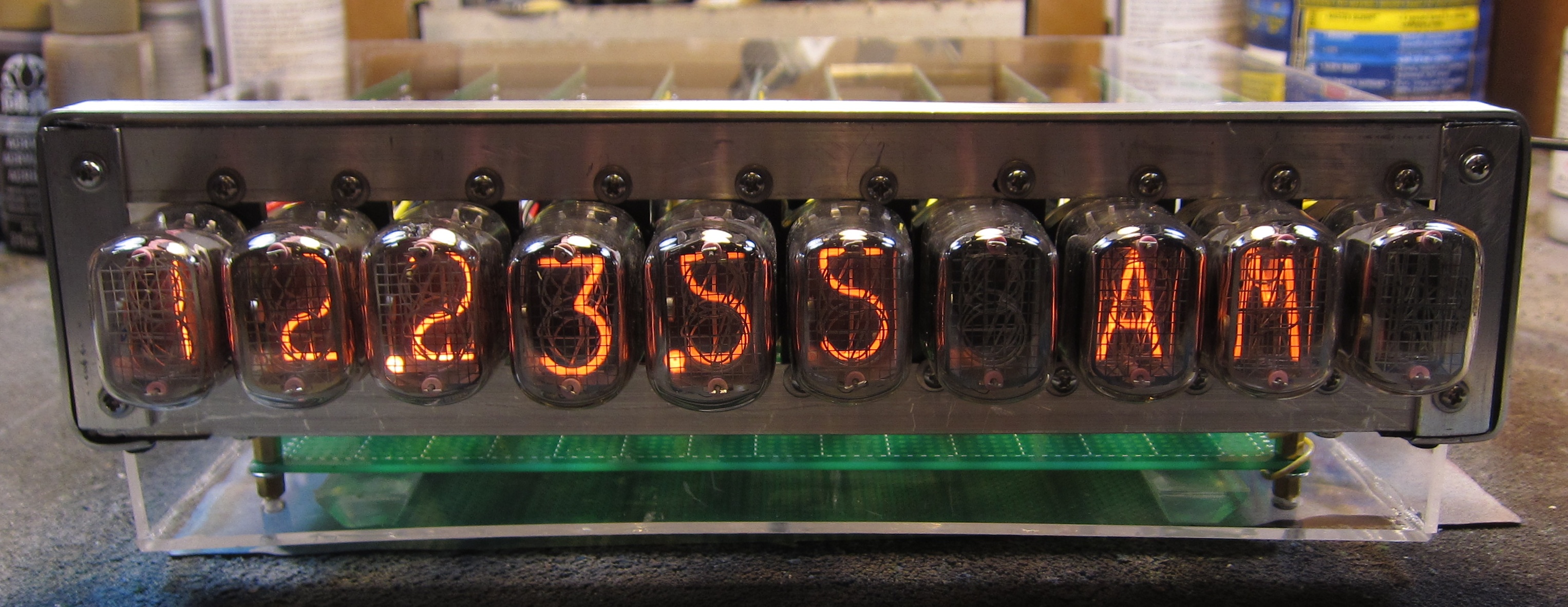
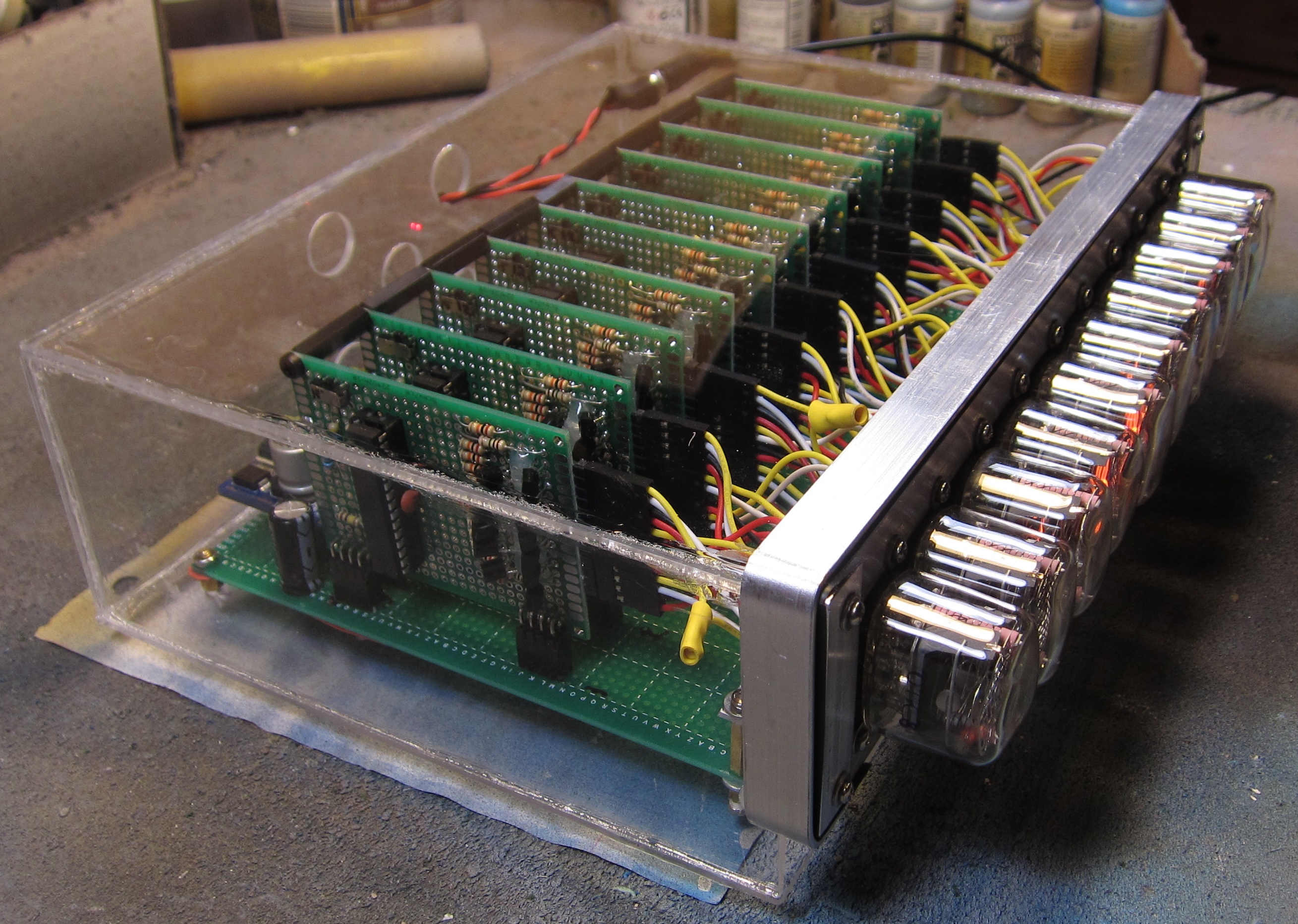
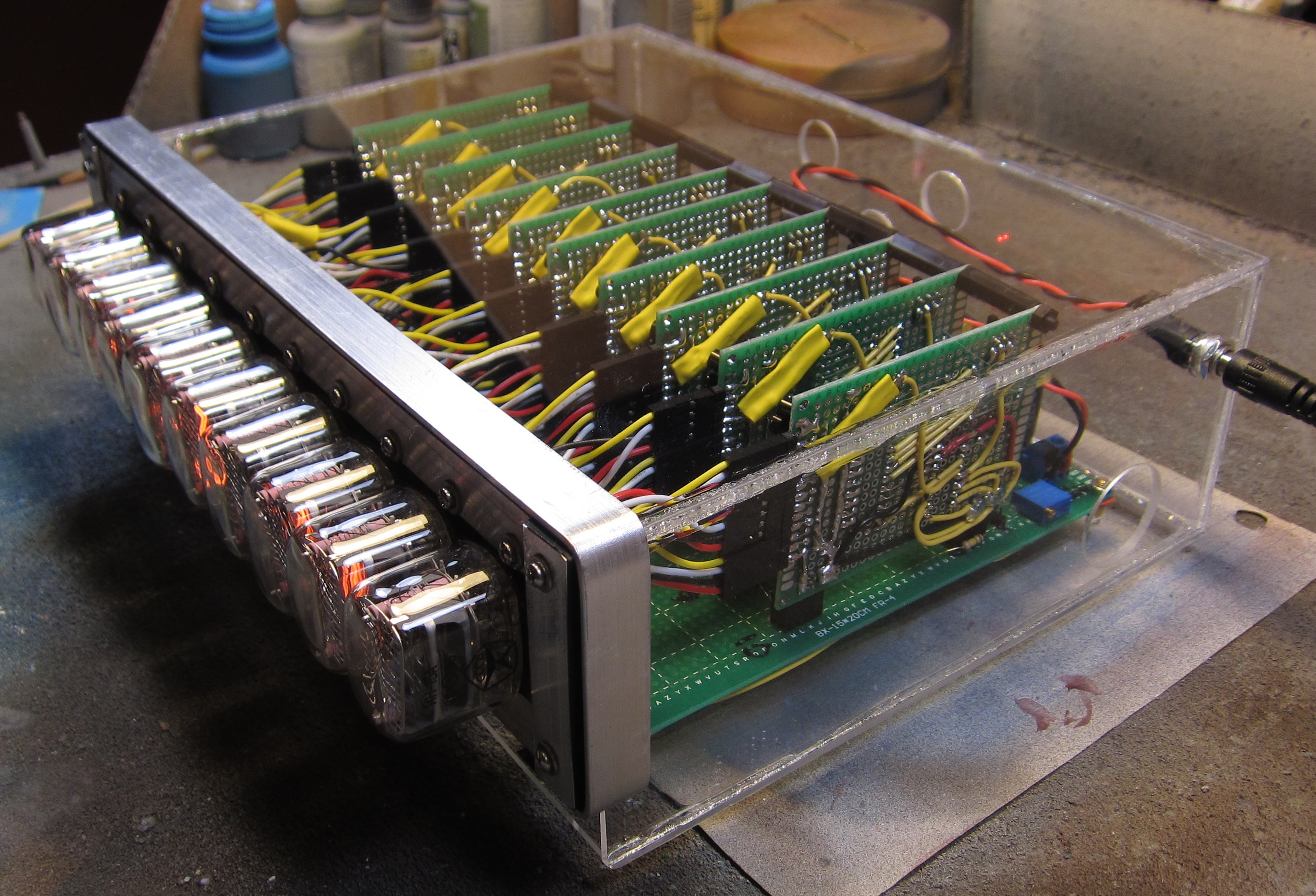
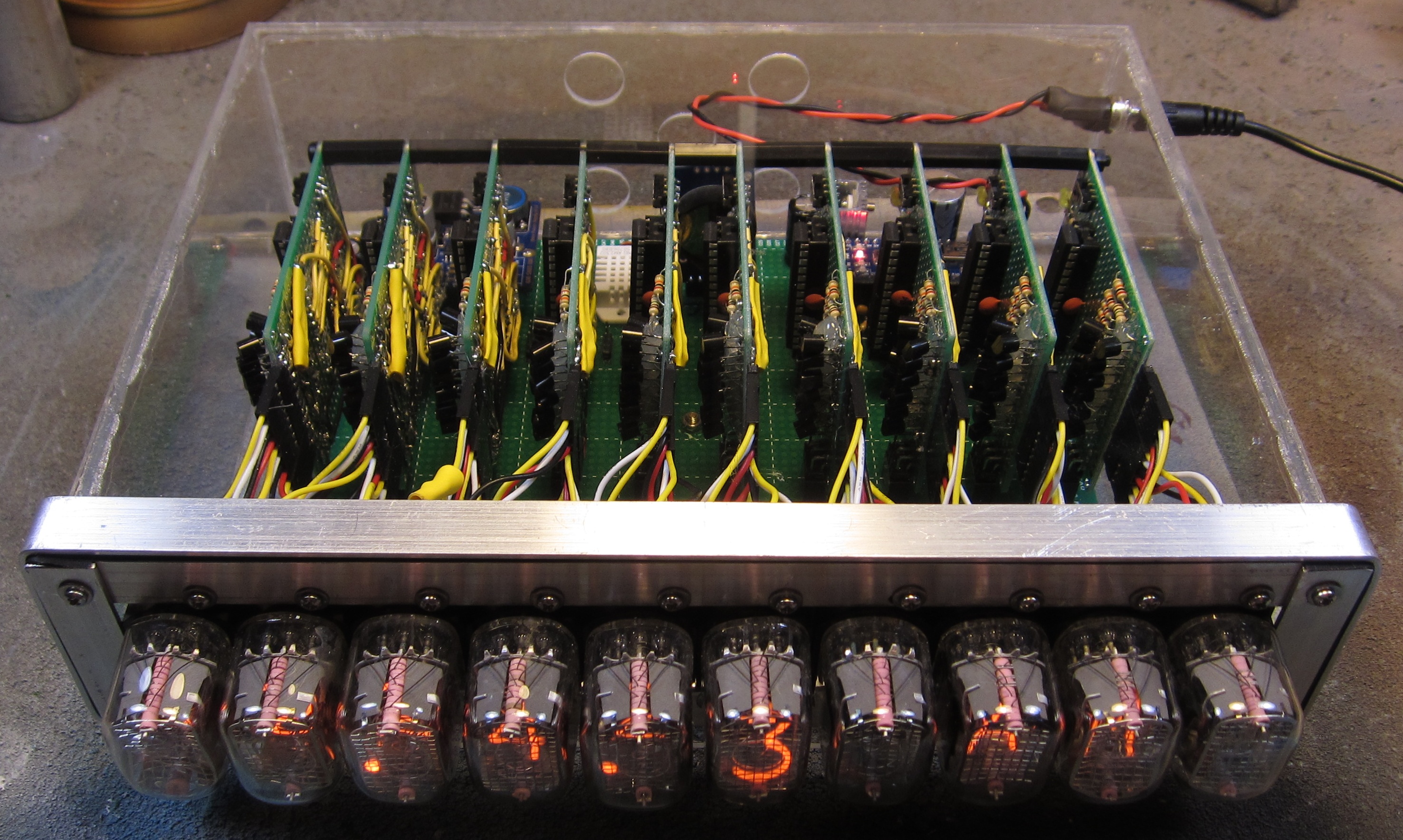
Not Your Average Nixie Clock
-
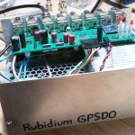
Rubidium GPSDO
