This project started as a way to increase the accuracy of a tuner I've been developing. The idea was that to get a more accurate lock on the fundamental frequency of a tone being tuned, you needed to reduce the noise on the signal as much as possible. That would mean that low noise techniques in the circuitry is essential, and a low noise microphone is just as important, but it also suggests that ambient noise and sound reflections could effect the tuner's reading. I conceived this acoustic isolation chamber as a place to stick in a microphone 'wearing' a pair of headphones, so that a pure sine wave derived from a high stability timebase could be fed directly into the microphone and tuner circuit for the most accurate test of the reliability of the tuner's circuitry.
Construction:
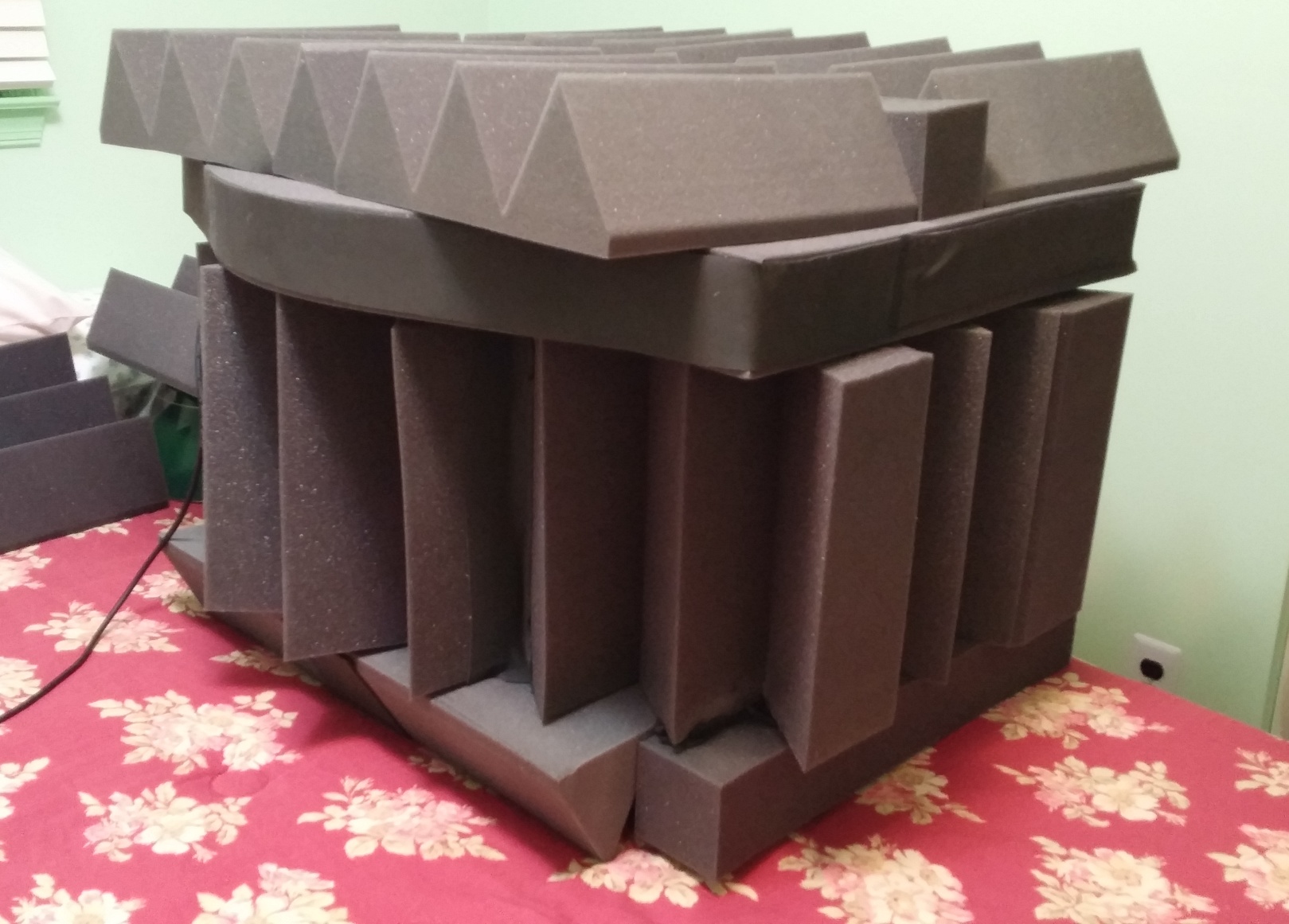
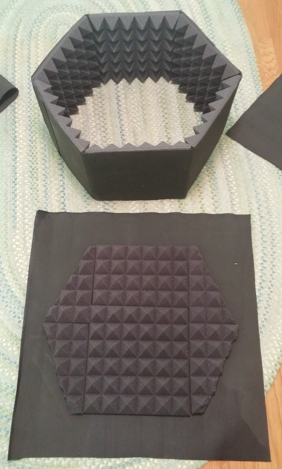
That meant that the chamber didn't have to be large and the performance requirement was 'as good as was practical', so I started looking around at potential materials and designs. To keep price down, I went with commercially available acoustic foam, for easy assembly I used a recommended spray adhesive (3M Super 77), and to optimize performance, I tried to design the chamber to be evenly insulated and near airtight. The basic design is an inward facing layer of 2 inch pyramid foam stuck to a high density 1/16" neoprene sheet that makes a near-sealed bag, then covering the outside with 4" wedge foam (for maximum absorption of ambient noise using standard sizes) and some 3" square foam strips for added structure.
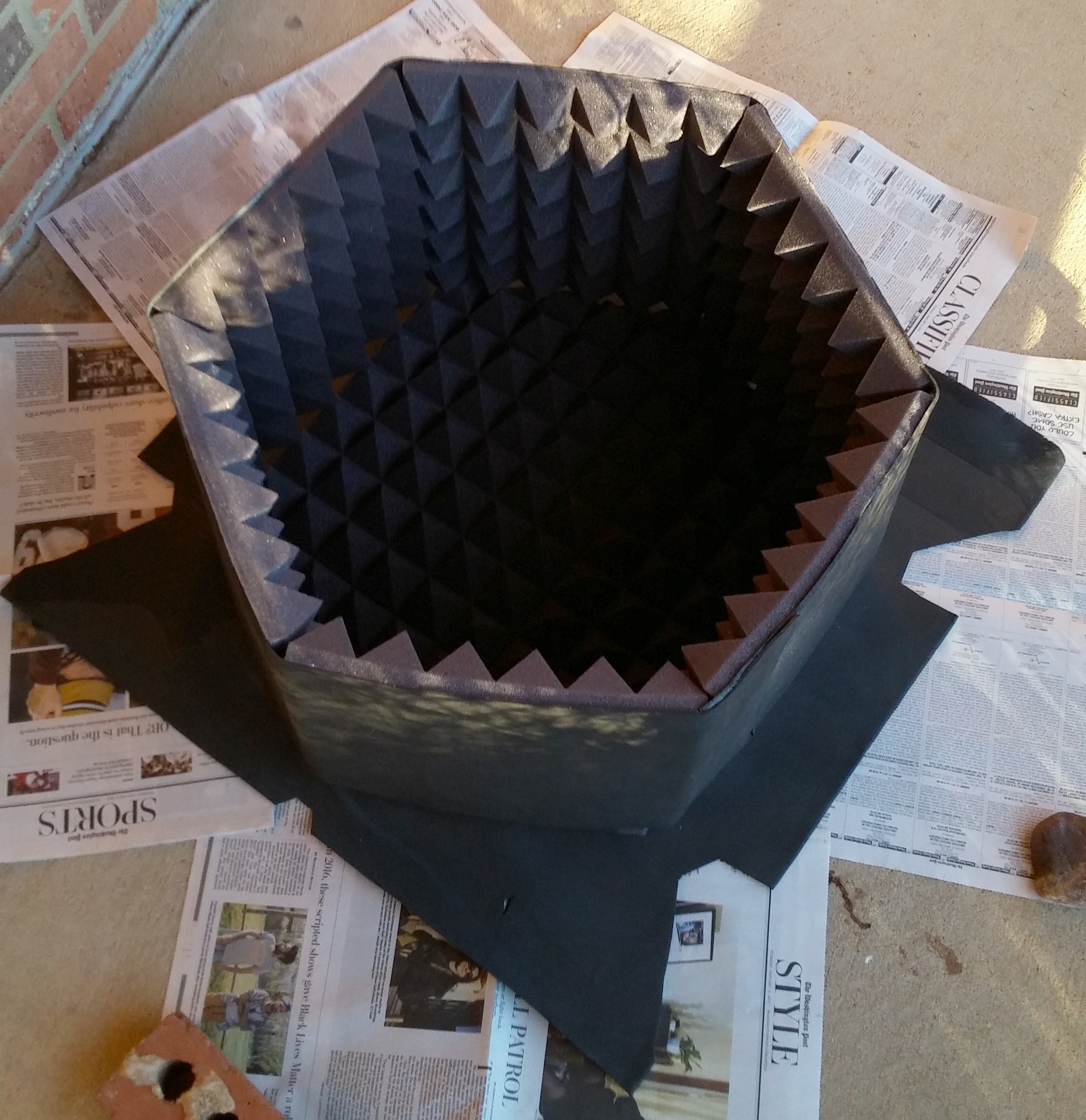
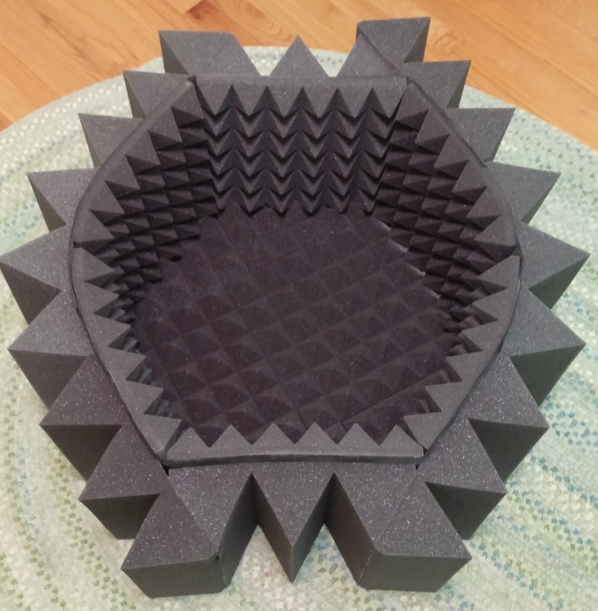
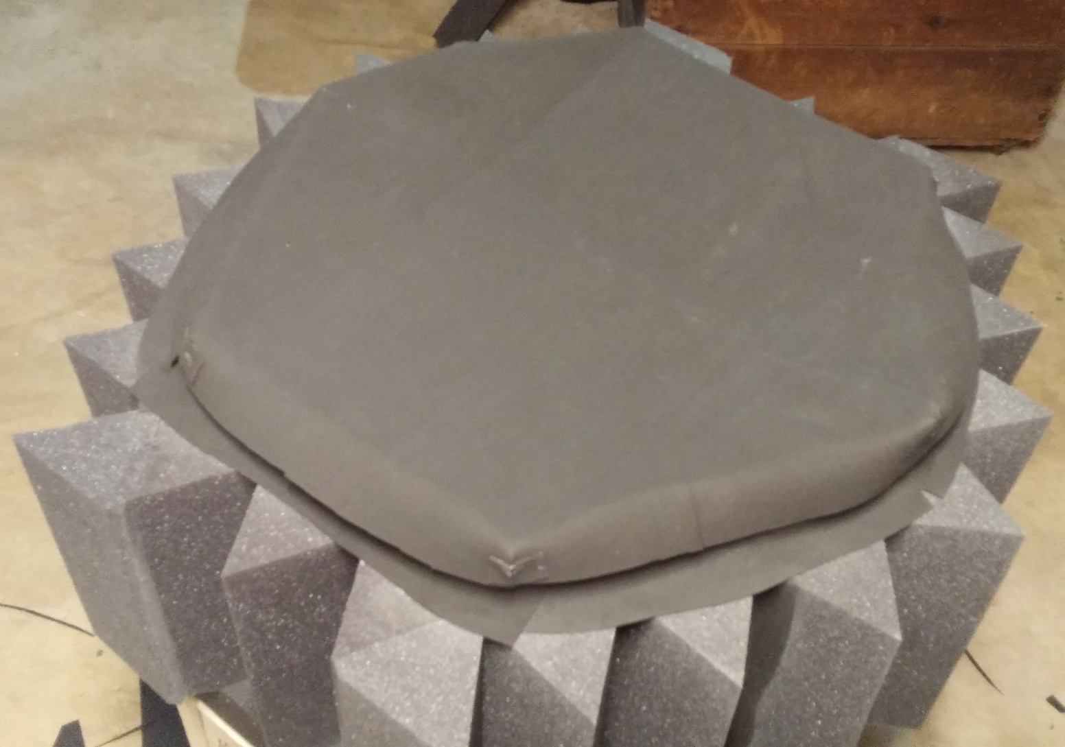
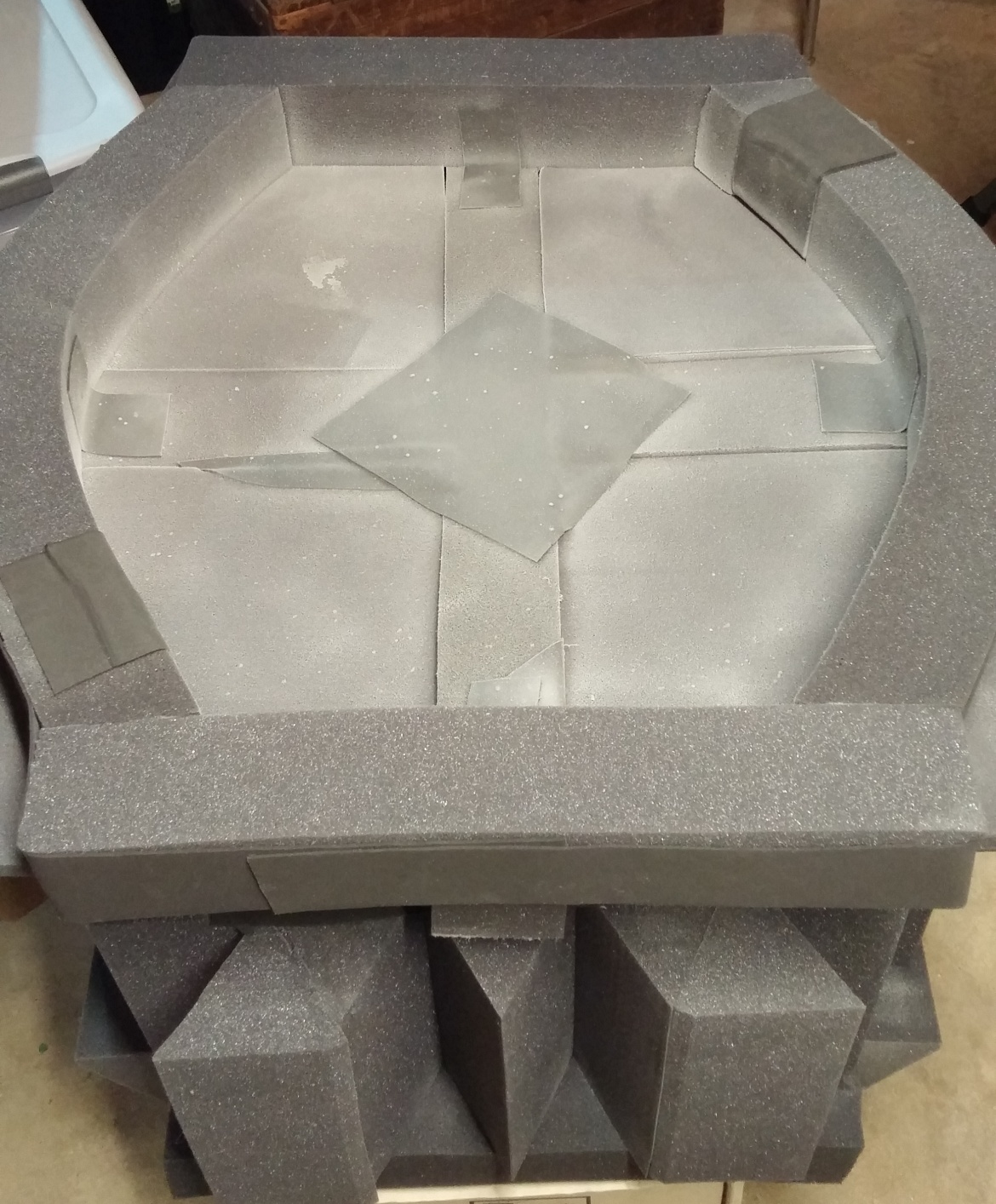
Construction started with a sheet of the neoprene layer with the outline of the bottom of the chamber glued to it in wedge foam. Then a long sheet of neoprene was stuck to six pyramid foam panels and glued into a hexagonal shape with the pyramids on the inside. Then I took the base section (with lots of overlap to ensure a good seal) and glued it to the hexagonal side walls. I then built up the 4" wedge foam sections on the outside (using a couple segments of neoprene to keep them from peeling away when flexed), and completing the base of the chamber with additional wedge foam and an I shaped arrangement of the square foam strips. To even up the portion that would be facing the lid, I used a strip of neoprene cut to fit the shape of the opening without creases and trimmed to be flush with the top of the inner pyramid foam panels, which protrude slightly from the wedges on the outside.
To make the top, I started making effectively a second base section like the beginning of the build, but left the overlapping sections short so that I could reinforce them and fold them over the inner part of the part it would slip over when completed, then I used that as a template to glue the folds accurately. Then I built a frame that was designed to go around the recessed area on the outside of the lower part and hold the lid part that was just built in place. This frame was meant to provide most of the structure for the lid, so i reinforced it with strips of neoprene On the outside face of the frame, I then added crossing segments and more panels of 4" wedge foam, to make a full exterior. For reinforcement I added some neoprene strips in certain places on the underside (inside face) of this exterior shell. Finally, I added some spacers for leveling and stability and glued in the inner lid portion (described at the beginning of making the lid) to the outer lid structure.
Testing:
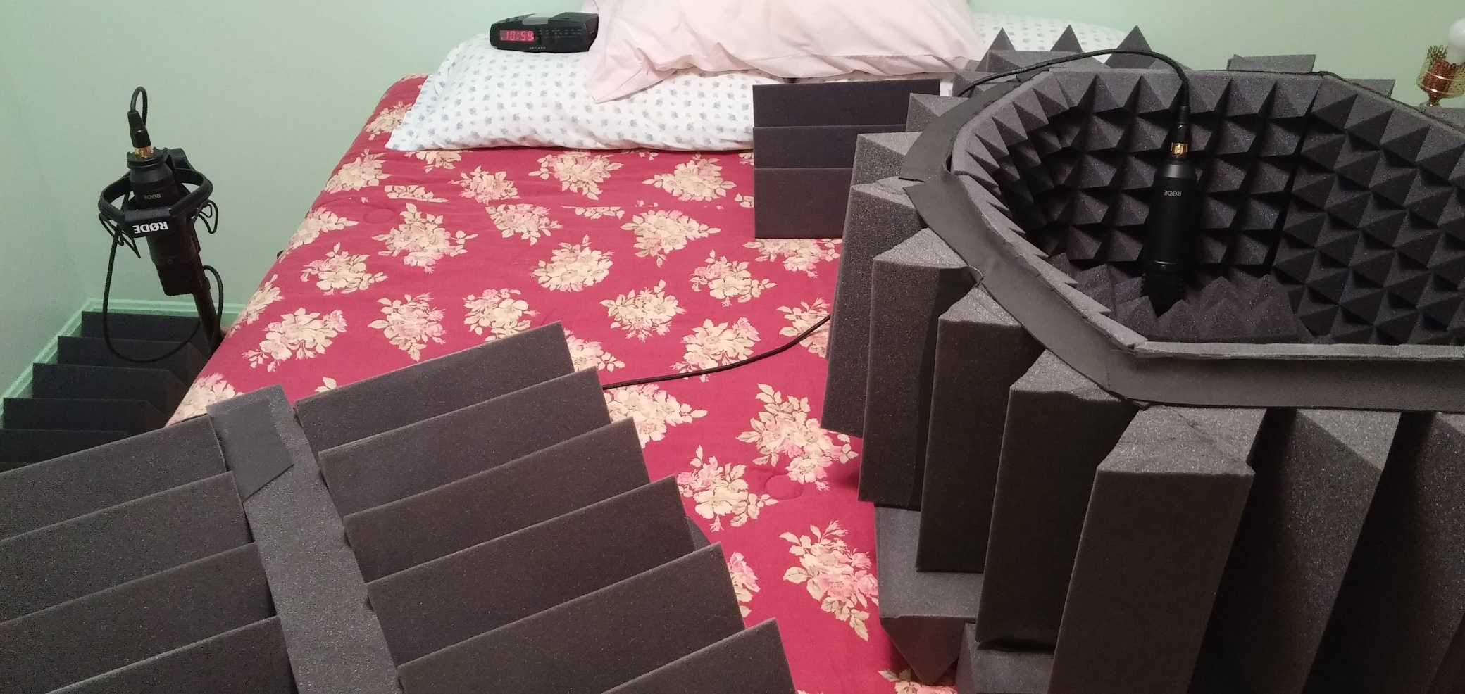
It's important for performance for the chamber to be sealed, but it's impossible to observe on your own since it's way too small to actually get into – but just holding the chamber near your head noticeably deadens the sound, and putting it over your head while lying down, while it looks very silly, gives you a reasonable approximation of what it sounds like inside. For a better test of its performance, I setup a pair of matching low noise mics, two Rode NT1s digitized through a Motu 624 interface, and then piped in a signal through a speaker for a source. The speaker used was an inexpensive M-Audio BX5a monitor , and was I'll comment at the end, using a better (better low response and more even frequency response) speaker would have resulted in more accurate data from the tests.
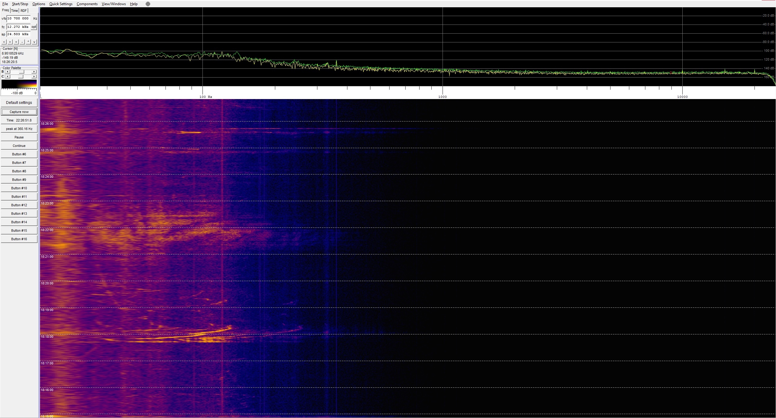
I first took some passive readings to compare the ambient noise of the room (a second floor bedroom, door closed, air conditioning off, on a bed), and some passive readings from a mic in the chamber in the same environment. I used the free Spectrum Lab software for a color coded spectragram, using these settings:
192kHz sampling
524288 FFT bins
Hanning window
4 bin smoothing
18dB of gain on the audio interface
Outside the chamber Inside the Chamber
Then to get some general active readings, I generated pink and white noise from Arta, played it at a loud volume through the speaker, and again captured the spectrum in Spectrum Lab.
This gave a good visualization on how the chamber performed, but I also wanted to see if I could generate a proper Bode plot for its performance. To make that, I used Steps (which came in the same package as Arta), and selected these settings:
400ms Integration time
200ms Transient time
250ms Intraburst time
1/48th Octave divisions (25 cents per step, for your musicians)
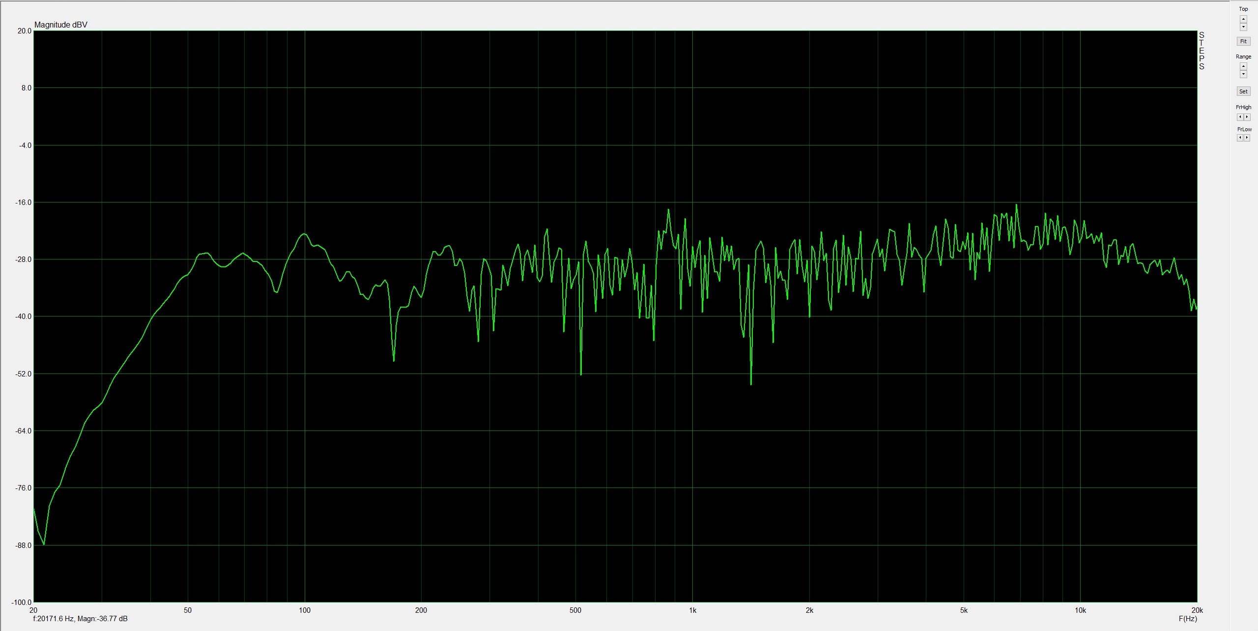
Outside of the chamber:
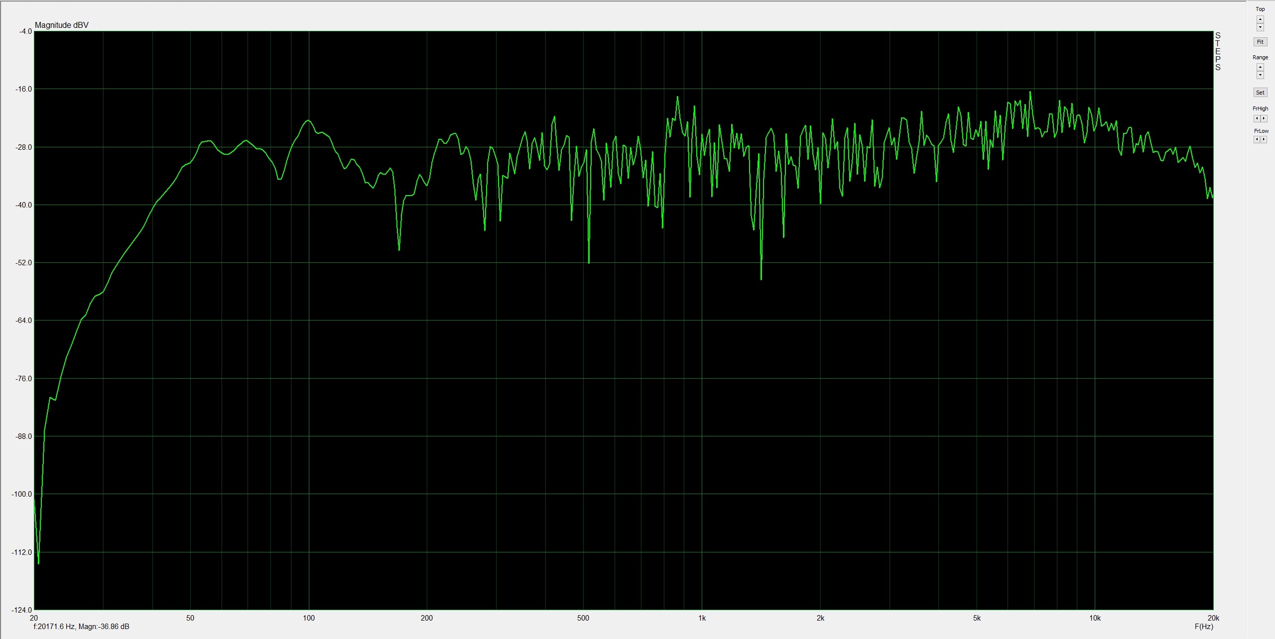
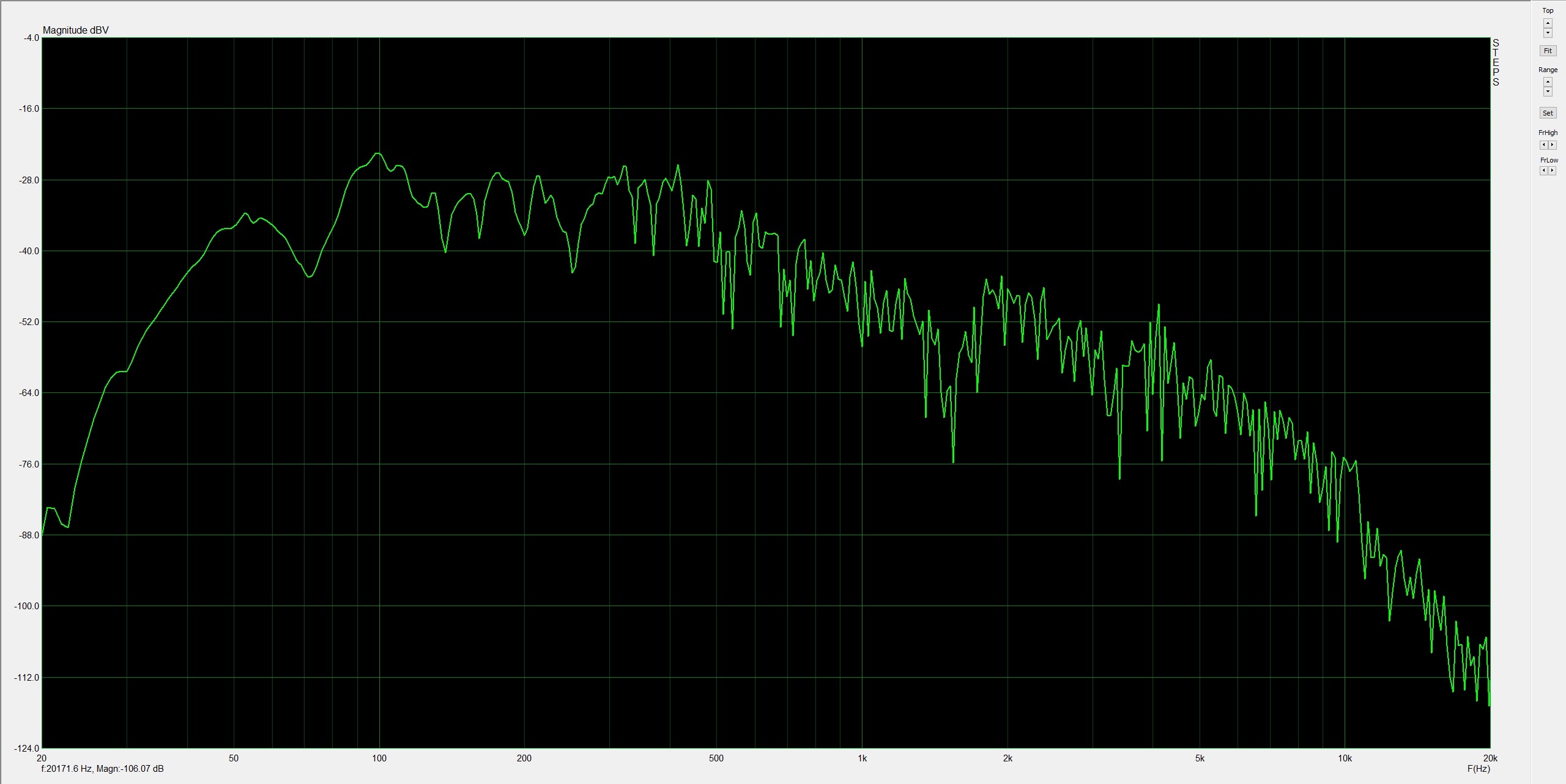
Inside of the chamber:
It's worth noting that to make sure of an even test, the mics were positioned the same distance from the speaker, at the same height, and rotated slightly to face it. The speaker was then aimed directly down the center fo the two mics, trying to reduce the impact of the directionality of the speaker on the readings.
Analysis:
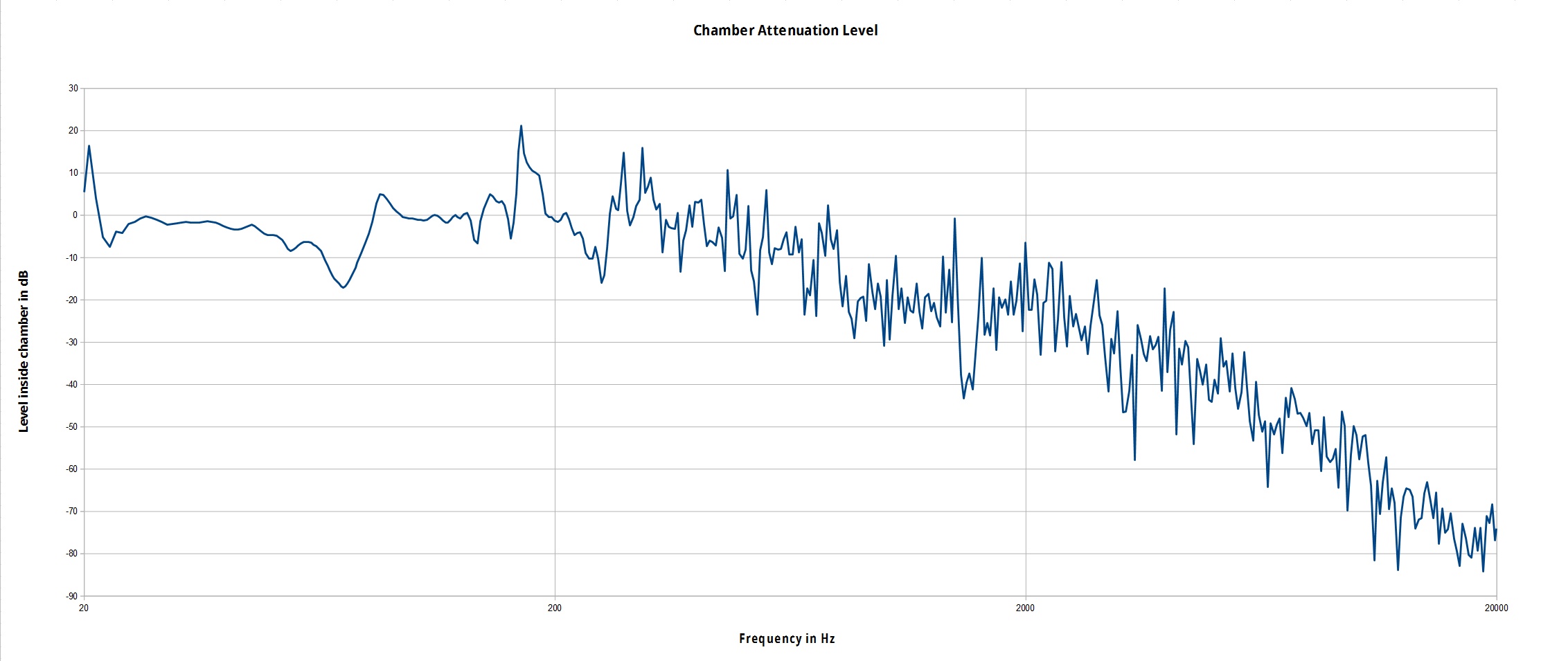
To reduce noise and inconsistency, I took two step response plots for the mic outside the chamber and the mic inside the chamber, then using the data recorded, averaged the two tests and subtracted the inner mic reading from the outer and plotted it in spreadsheet software. This generated a frequency response plot to quantify the attenuation of the chamber at different frequencies.
As you can see, however, the testing done was not extremely accurate. Most of this is attributable to two things: a comparatively low quality source speaker (very poor low frequency response, somewhat inconsistent spikes in higher frequencies), and the inability to record both channels at once. Because of the software being used, I could only capture the input from one mic at a time, which meant that even though the tests were done with very similar external conditions, they were made sequentially and are not identical – a bit of external noise or a quirk in speaker performance in one test may not have showed happened in the next test.
Problems aside, there is usable trend data to show the performance of the chamber. It's easiest to see in the generated noise spectragrams, but the chamber's attenuation is best at high frequencies and starts rolling off around 200Hz. In the step response generated Bode plot, the point where the rolloff is noticeable is closer to 400Hz, but this is mostly because of the inconsistency of the peaks of the readings. This is expected, as low frequencies, with their longer wavelengths, are near impossible to completely eliminated with only a few inches of foam. Lower frequencies also transmit better through walls and through the floor, so there is more low frequency noise just from the nature of the construction of the room I was testing in. As the frequency increases, however, the chamber works quite well, and it attenuates to the noise floor of the microphone before you get to the 20kHz limit of human hearing (from listening to the sweep testing, mine ends around 17.5kHz). Looking at the spectragrams, there is some limited attenuation in lower frequencies, but a full evaluation of the low end (below 60Hz) isn't possible without a speaker capable of generating lower frequencies well.
While some of the peaks seen in testing are artifacts of the speaker being used, some are also because of the geometry of the chamber and of the room. The room had standard drywall sides, and while there was some extra acoustic foam around, there were still many areas that are reflective to sound and even a handful of parts loose enough to rattle in testing – especially between about 80 and 130Hz. My understanding and mathematical capabilities aren't sophisticated enough to make a real evaluation of what about the dimensions and construction of the chamber and the room gave me the results I saw, and especially without a better sound source, I'm not sure data good enough to be significant for analyzing those elements can even be found in these tests.
As a final demo, I recorded a brief bit of speaking and pink noise using both microphones at the same time, one inside the chamber and one outside, so that after all the numbers, you can hear the difference the chamber makes for yourself. The first track switches between the two to hear them side by side, and then the full recordings from each mic are available below that.
Switching between both mics
Outer mic
Inner mic
Designing, building, and testing this chamber was an interesting project for me, I hope if you're considering something similar, this was useful to your project, or if you were just curious, this was an interesting read. I'll see if the chamber can really make a difference for its intended purpose, testing a custom high precision tuner, when the electronics for the tuner reach their final revision.